Welcome to the world of piping design and engineering — where steel arteries carry life-sustaining fluids through the heart of every industrial plant. From chemical factories to power plants, piping systems make it all possible. But designing these networks isn’t just about connecting pipes — it’s a blend of engineering precision, material science, and flow mastery. In this blog, we’ll break down the core components, design principles, industry codes, and real-world considerations that turn a basic pipe sketch into a reliable, code-compliant, and efficient system.

What is Piping Engineering?
Imagine an industrial plant as a living body. The tanks are organs, the pumps are the heart — and piping systems are the veins and arteries that carry the lifeblood — chemicals, steam, oil, water, gases — from one place to another. Piping engineering is the specialized branch of engineering that focuses on the design, analysis, layout, and integrity of these systems to ensure safe, efficient, and reliable transport.
Key Components of a Piping System
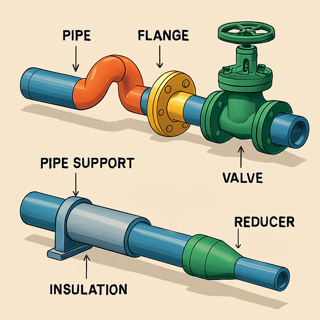
A typical piping system consists of the following elements:
– Pipes: Transport the fluid.
– Fittings: Change direction, connect or reduce pipe sizes.
– Valves: Control or isolate flow.
– Flanges: Join pipes and allow disassembly.
– Supports: Hold pipes in place and manage thermal movement.
– Insulation: Reduces heat loss or gain.
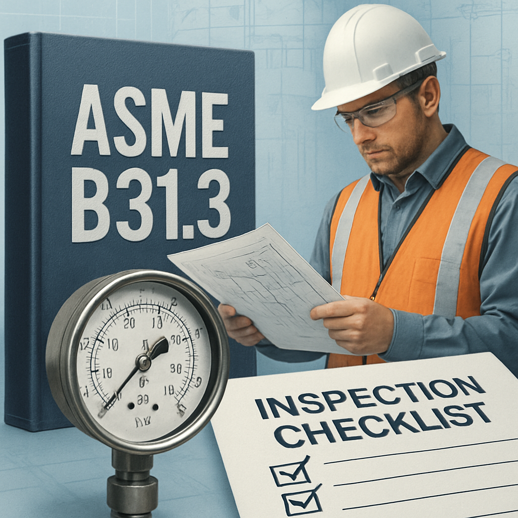
Codes and Standards
Designing safe and reliable piping requires strict adherence to codes and standards. The most widely used are:
– ASME B31.3 – Process Piping
– ASME B31.1 – Power Piping
– ASME B31.4 / B31.8 – Pipeline Transport Systems
These codes define design pressure, temperature, material requirements, stress limits, and inspection protocols.
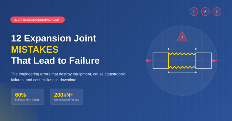
Pipe Stress and Flexibility
Pipes expand and contract with temperature. Poor design can lead to cracking or failure. Stress analysis evaluates:
– Thermal expansion
– Weight and sustained loads
– Seismic and wind loads
– Occasional loads
Software like CAESAR II is used to model and validate piping stress.

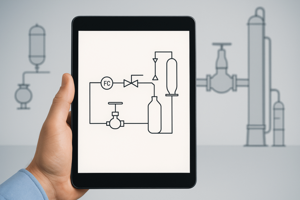
Piping Layout and P&IDs
The piping layout defines the physical route of pipes, considering accessibility, support, and safety. It’s developed based on P&IDs (Piping and Instrumentation Diagrams), which show the schematic connections of equipment, pipes, valves, and instruments.
Good layout minimizes pressure drops, eases maintenance, and enhances safety.
Conclusion
Piping design and engineering is a foundational skill for any mechanical or process engineer working in industry. It combines deep technical knowledge, regulatory understanding, and practical creativity.
Stay tuned for upcoming blogs where we’ll explore pipe stress analysis, real project examples, and essential software tools in more detail.
If you’re passionate about learning piping the right way — welcome aboard!